Build a Wi-Fi Weather Station with ESP32
📖 Overview
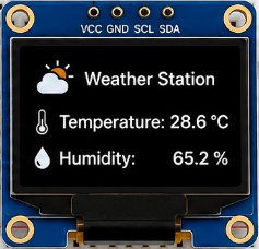
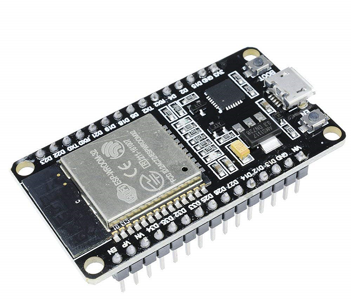
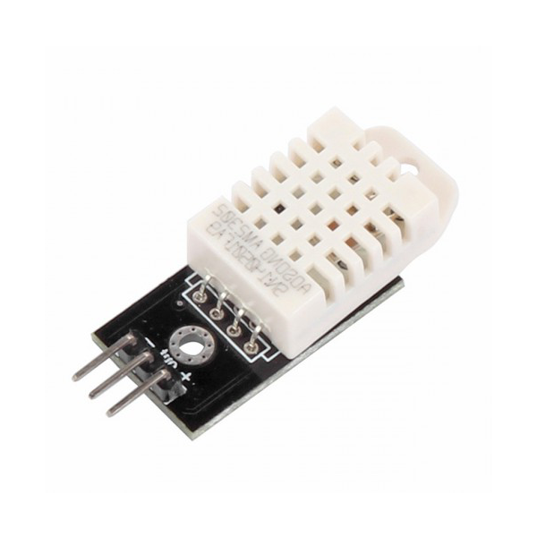
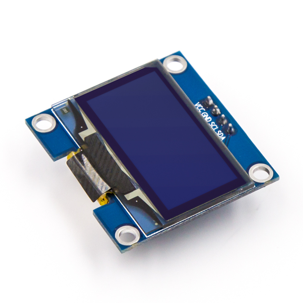
Welcome to the Build a Wi-Fi Weather Station with ESP32 course, where you will learn to design and build a fully functional weather station that connects to the internet. In this course, you will work with the ESP32 microcontroller, a DHT22 sensor to measure temperature and humidity, and a 0.96" OLED display to show live readings.
Throughout the course, you will gain hands-on experience with reading sensor data, connecting a microcontroller to Wi-Fi, and driving a display. You will learn how to integrate these components into a single, cohesive project that showcases your understanding of IoT and embedded systems concepts. By the end of the course, you will have a working weather station that can provide real-time temperature and humidity readings, which can be accessed remotely over Wi-Fi.
The skills you learn in this course will be valuable for a wide range of applications, from home automation and environmental monitoring to industrial control systems and beyond. Some key topics covered include:
- Setting up and programming the ESP32 microcontroller
- Interfacing with the DHT22 sensor to read temperature and humidity data
- Connecting to Wi-Fi and sending data to the cloud
- Driving the 0.96" OLED display to show live sensor readings
By building a Wi-Fi-connected weather station, you will develop a deeper understanding of the intersection of hardware and software in IoT and embedded systems, and gain practical experience with the tools and technologies used in these fields. This course is designed for beginners, and no prior experience with ESP32, DHT22, or OLED displays is required.
🔌 Components & Wiring Guide
Components and Their Purposes
- ESP32: Microcontroller for connecting to Wi-Fi and controlling peripherals
- DHT22 sensor: Reads temperature and humidity data
- 0.96" OLED display: Displays live temperature and humidity readings
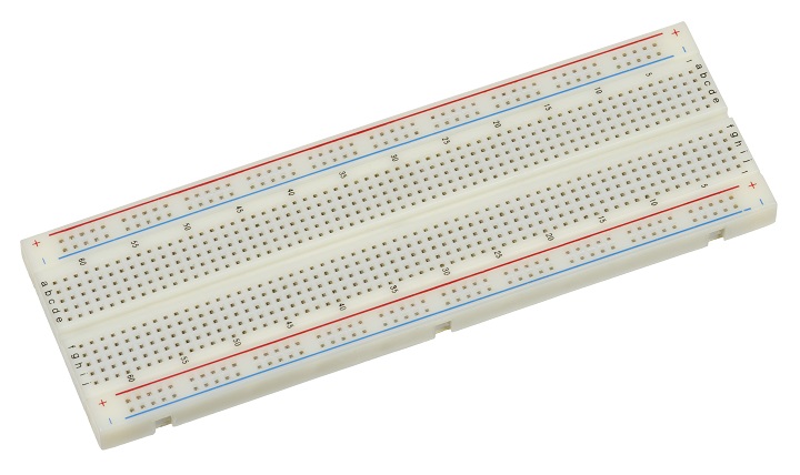
- Breadboard: Platform for connecting and organizing components
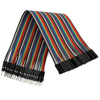
- Jumper wires: Connect components to each other and the breadboard
Wiring and Connection Guide
To connect the components, start by placing the ESP32 and OLED display on the breadboard. Connect the ESP32's VIN pin to the breadboard's power rail and the GND pin to the ground rail. Next, connect the DHT22 sensor's VCC pin to the breadboard's power rail and the GND pin to the ground rail. The DHT22 sensor's signal pin should be connected to one of the ESP32's digital pins, such as GPIO17. The OLED display's VCC and GND pins should be connected to the breadboard's power and ground rails, respectively. The OLED display's SCL and SDA pins should be connected to the ESP32's SCL and SDA pins, which are typically GPIO22 and GPIO21, respectively.| Component | Pin | Connection |
|---|---|---|
| ESP32 | VIN | Breadboard power rail |
| ESP32 | GND | Breadboard ground rail |
| DHT22 sensor | VCC | Breadboard power rail |
| DHT22 sensor | GND | Breadboard ground rail |
| DHT22 sensor | Signal | ESP32 GPIO17 |
| OLED display | VCC | Breadboard power rail |
| OLED display | GND | Breadboard ground rail |
| OLED display | SCL | ESP32 GPIO22 |
| OLED display | SDA | ESP32 GPIO21 |
🛠️ Step-by-Step Guide
Introduction to the Project
In this project, we will build a Wi-Fi-connected weather station using the ESP32 microcontroller, DHT22 sensor, and a 0.96" OLED display. The weather station will read temperature and humidity data from the DHT22 sensor and display live readings on the OLED screen.
Step 1: Setting Up the Hardware Components
To start, make sure you have all the necessary hardware components, including the ESP32, DHT22 sensor, 0.96" OLED display, breadboard, and jumper wires. Begin by placing the ESP32 and OLED display on the breadboard.
Connect the OLED display to the ESP32 according to the following pin connections: VCC to 3V3, GND to GND, SCL to GPIO22, and SDA to GPIO21.
Step 2: Connecting the DHT22 Sensor
Next, connect the DHT22 sensor to the ESP32. The DHT22 sensor has four pins: VCC, GND, DATA, and NC. Connect the VCC pin to 3V3 on the ESP32, the GND pin to GND, and the DATA pin to any available digital pin on the ESP32 (e.g., GPIO23).
Step 3: Wiring Recap
Here's a recap of the wiring connections:
- OLED display: VCC to 3V3, GND to GND, SCL to GPIO22, SDA to GPIO21
- DHT22 sensor: VCC to 3V3, GND to GND, DATA to GPIO23
Step 4: Installing the Required Libraries
Before uploading the firmware, make sure to install the required libraries, including the WiFi, DHT, and SSD1306 libraries.
Step 5: Uploading the Firmware
Now, upload the firmware to the ESP32 using the Arduino IDE. Make sure to select the correct board (ESP32) and serial port.
The firmware code should include the following:
Initialization of the Wi-Fi connection, DHT22 sensor, and OLED display. Reading of temperature and humidity data from the DHT22 sensor. Displaying live readings on the OLED screen.
Step 6: Testing the Weather Station
Once the firmware is uploaded, test the weather station by checking the OLED display for live temperature and humidity readings.
Make sure the ESP32 is connected to your Wi-Fi network and that the DHT22 sensor is reading accurate data.
Step 7: Troubleshooting Tips
If you encounter any issues during the build process, here are some troubleshooting tips:
- Check the wiring connections for any loose or incorrect connections.
- Verify that the ESP32 is properly connected to your Wi-Fi network.
- Ensure that the DHT22 sensor is properly connected to the ESP32 and that the firmware is configured to read data from the correct pin.
Conclusion
With these steps, you should now have a fully functional Wi-Fi-connected weather station using the ESP32, DHT22 sensor, and OLED display. You can further enhance this project by adding more features, such as data logging or cloud connectivity.
💻 Sample Code
#include <WiFi.h>
#include <Wire.h>
#include <Adafruit_SSD1306.h>
#include <Adafruit_DHT.h>

// Define constants for Wi-Fi connection
const char* ssid = "your_wifi_ssid";
const char* password = "your_wifi_password";

// Define constants for DHT22 sensor
const int dhtPin = 2;
const int dhtType = DHT22;

// Define constants for OLED display
const int oledScl = 22;
const int oledSda = 21;

// Initialize DHT22 sensor and OLED display
DHT dht(dhtPin, dhtType);
Adafruit_SSD1306 display = Adafruit_SSD1306(128, 64, &Wire);

void setup() {
  // Initialize serial communication
  Serial.begin(115200);

  // Initialize OLED display
  display.begin(SSD1306_SWITCHCAPVCC, 0x3C);
  display.clearDisplay();
  display.setTextSize(1);
  display.setTextColor(WHITE);

  // Connect to Wi-Fi
  WiFi.begin(ssid, password);
  while (WiFi.status() != WL_CONNECTED) {
    delay(1000);
    Serial.println("Connecting to WiFi...");
  }
  Serial.println("Connected to WiFi");
  Serial.println("IP address: ");
  Serial.println(WiFi.localIP());

  // Initialize DHT22 sensor
  dht.begin();
}

void loop() {
  // Read temperature and humidity from DHT22 sensor
  float temperature = dht.readTemperature();
  float humidity = dht.readHumidity();

  // Check if readings are valid
  if (isnan(temperature) || isnan(humidity)) {
    Serial.println("Failed to read from DHT22 sensor");
    return;
  }

  // Display temperature and humidity on OLED screen
  display.clearDisplay();
  display.setCursor(0, 0);
  display.print("Temperature: ");
  display.print(temperature);
  display.print(" C");
  display.setCursor(0, 20);
  display.print("Humidity: ");
  display.print(humidity);
  display.print(" %");
  display.display();

  // Print temperature and humidity to serial console
  Serial.print("Temperature: ");
  Serial.print(temperature);
  Serial.print(" C");
  Serial.print(" Humidity: ");
  Serial.print(humidity);
  Serial.println(" %");

  // Wait 1 second before taking next reading
  delay(1000);
}
📝 Check Your Understanding
1. What is the primary function of the DHT22 sensor in the Wi-Fi weather station project?
   a) To connect the ESP32 to Wi-Fi
   b) To display temperature and humidity readings on the OLED screen
   c) To read temperature and humidity data from the environment
   d) To power the ESP32 board
   Answer: c

2. Which of the following is a required step to connect the ESP32 to Wi-Fi?
   a) Importing the DHT22 library
   b) Initializing the OLED display
   c) Configuring the Wi-Fi credentials and establishing a connection
   d) Reading sensor data from the DHT22
   Answer: c

3. How is the 0.96" OLED display typically connected to the ESP32?
   a) Using jumper wires to the breadboard, which is then connected to the ESP32
   b) Directly soldering the display to the ESP32 board
   c) Connecting the display to a separate power source
   d) Using a USB cable to connect the display to the ESP32
   Answer: a

4. What is the purpose of including the DHT22 library in the ESP32 code?
   a) To drive the OLED display
   b) To connect the ESP32 to Wi-Fi
   c) To read temperature and humidity data from the DHT22 sensor
   d) To configure the breadboard
   Answer: c

5. What should be displayed on the 0.96" OLED screen when the Wi-Fi weather station is fully functional?
   a) The IP address of the ESP32
   b) The Wi-Fi credentials
   c) Live temperature and humidity readings
   d) The DHT22 sensor data in binary format
   Answer: c
Need the Components for This Project?
If you don't already have the components listed above, you can buy genuine Arduino, ESP32, Raspberry Pi, sensors, and other electronic components from SoftTech Supply Shop, with fast delivery across Kigali and other parts of Rwanda.
← Browse more Arduino & IoT tutorialsRelated Tutorials
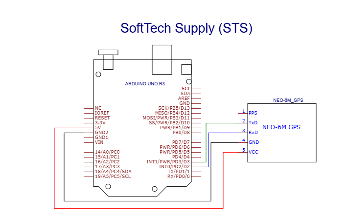
How to use ATGM336H GPS+BDS Module with Antenna with an Arduino Uno
ATGM336H GPS+BDS Module with Antenna, Arduino Uno R3 With USB Cable, Male to Male Jumper Wires, Breadboard 830 Point Solderless
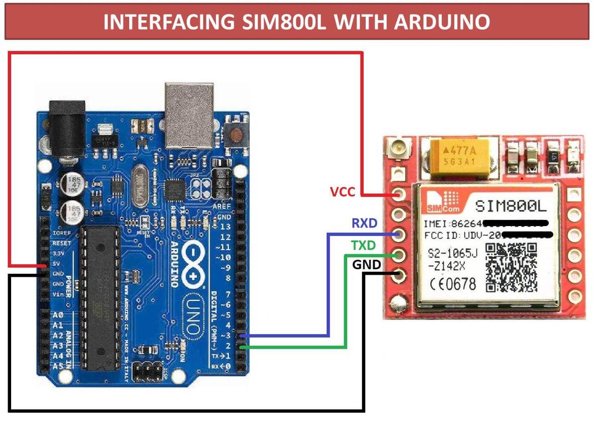
How to connect GSM SIM800L with Arduino Uno to send an SMS or make a Call
Arduino UNO R3 removable IC Chip with USB CABLE, Smallest SIM800L GPRS GSM, Male to Female jumper wires
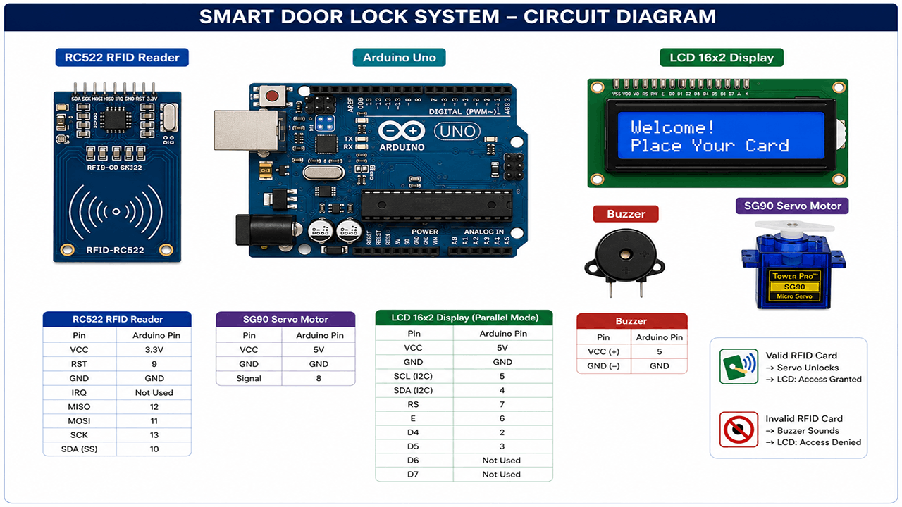
Smart Door Lock with RFID and Servo Motor
Arduino UNO R3 removable IC Chip with USB CABLE, RFID Reader Module 13.56Mhz, SG90 9g Mini Micro Servo Motor, 16x2LCD Display with I2C Interface, 5v active buzzer, Breadboard 830 Point Solderless, Male to Male Jumper Wires
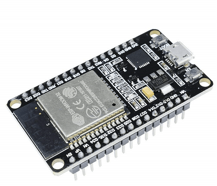
How to connect esp32 on WiFi
ESP32 ESP-32 Wireless WiFi Bluetooth Development Board, smartphone, or any other device that can shared WiFi