Build simple project with arduino
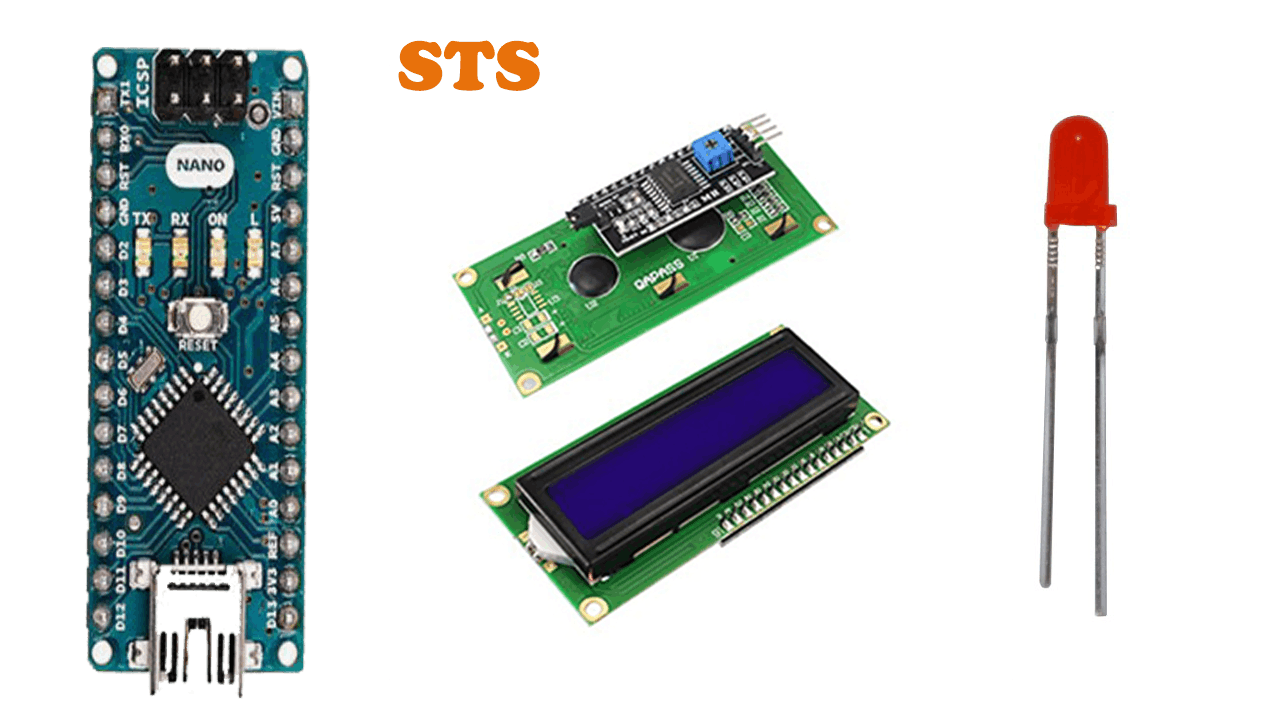
Components used:
📖 Overview
Welcome to the Build Simple Project with Arduino course, designed for beginners looking to dive into the world of Internet of Things (IoT) and embedded systems. In this course, you will learn how to build a simple yet interactive project using an Arduino Nano, an LCD I2C display, and an LED. The primary goal of this project is to control the LED using the Arduino board, with the LCD display providing visual feedback and user interaction.
Through this project, you will gain hands-on experience with programming and electronics, learning the fundamentals of Arduino and its applications. You will understand how to connect and configure the hardware components, write and upload code to the Arduino board, and troubleshoot common issues. The course will cover the basics of Arduino programming, including variables, data types, loops, and conditional statements, as well as how to work with digital and analog inputs and outputs.
The skills and knowledge you acquire in this course will be useful in a wide range of applications, from home automation and robotics to wearables and environmental monitoring. You will learn how to:
- Connect and configure the Arduino Nano, LCD I2C display, and LED
- Write and upload code to the Arduino board using the Arduino IDE
- Control the LED using digital outputs and user input from the LCD display
- Troubleshoot common issues and debug your code
By the end of this course, you will have a working project that demonstrates your understanding of Arduino programming and electronics. You will be able to apply the skills and knowledge you have gained to more complex projects, exploring the endless possibilities of IoT and embedded systems. Whether you are a hobbyist, student, or professional, this course will provide a solid foundation for your future projects and endeavors.
🔌 Components & Wiring Guide
Components List
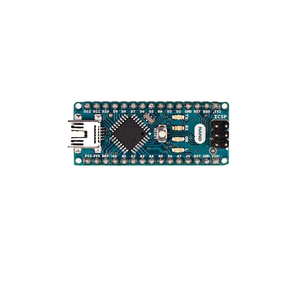
- Arduino Nano: Microcontroller board for executing code and controlling peripherals
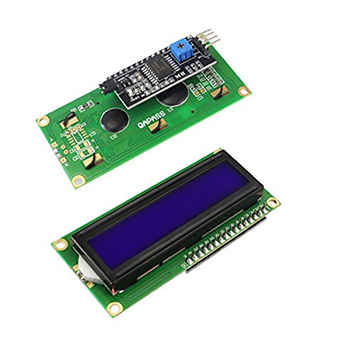
- LCD I2C: Liquid Crystal Display module for showing text and numbers using I2C communication protocol
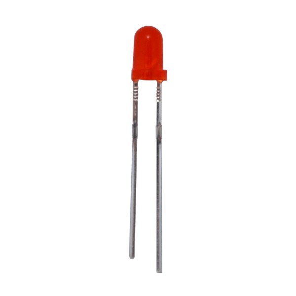
- LED: Light Emitting Diode for visual indication of output
Wiring Guide
To connect the components, follow these steps: First, identify the pins on the Arduino Nano. The LED will be connected to one of the digital pins. For this example, let's use digital pin 9. Connect the positive leg (anode) of the LED to digital pin 9 on the Arduino Nano. Then connect the negative leg (cathode) of the LED to one end of a resistor. The other end of the resistor should be connected to one of the GND pins on the Arduino Nano. Next, let's connect the LCD I2C module. The LCD I2C module typically has four pins: VCC, GND, SDA, and SCL. Connect the VCC pin of the LCD I2C module to the 5V pin on the Arduino Nano. Connect the GND pin of the LCD I2C module to one of the GND pins on the Arduino Nano. Connect the SDA pin of the LCD I2C module to the Analog Input 4 (A4) pin on the Arduino Nano, which is the SDA pin for I2C communication. Finally, connect the SCL pin of the LCD I2C module to the Analog Input 5 (A5) pin on the Arduino Nano, which is the SCL pin for I2C communication.Connection Summary
| Component | Pin | Connection |
|---|---|---|
| LED (anode) | Digital 9 | Arduino Nano |
| LED (cathode) | Resistor | GND on Arduino Nano |
| LCD I2C (VCC) | 5V | Arduino Nano |
| LCD I2C (GND) | GND | Arduino Nano |
| LCD I2C (SDA) | A4 | Arduino Nano |
| LCD I2C (SCL) | A5 | Arduino Nano |
🛠️ Step-by-Step Guide
Introduction to the Project
In this beginner-friendly course, we will be building a simple project using an Arduino Nano to control an LED. The project will also include an LCD I2C display to show the status of the LED.
Step 1: Setting Up the Hardware Components
To start, make sure you have all the necessary hardware components: Arduino Nano, LCD I2C, and an LED. The LCD I2C will be used to display the status of the LED, and the Arduino Nano will be the brain of the operation, controlling the LED.
Step 2: Wiring the Components
Now, let's move on to wiring the components. The wiring process is straightforward:
- Connect the VCC pin of the LCD I2C to the 5V pin on the Arduino Nano.
- Connect the GND pin of the LCD I2C to the GND pin on the Arduino Nano.
- Connect the SDA pin of the LCD I2C to the A4 pin on the Arduino Nano.
- Connect the SCL pin of the LCD I2C to the A5 pin on the Arduino Nano.
- Connect the anode (positive leg) of the LED to a digital pin on the Arduino Nano, for example, pin 9.
- Connect the cathode (negative leg) of the LED to the GND pin on the Arduino Nano through a resistor.
Step 3: Writing the Firmware
Next, we will write the firmware for the Arduino Nano. We will use the Arduino IDE to write and upload the code.
The code will include the Wire library for I2C communication and the library for the LCD I2C.
Step 4: Uploading the Firmware
To upload the firmware, connect the Arduino Nano to your computer using a USB cable. Open the Arduino IDE, select the correct board and port, and upload the code.
Step 5: Testing the Project
After uploading the firmware, it's time to test the project. Turn on the LED using the LCD I2C display and verify that it's working as expected.
You can use the LCD I2C display to send commands to the Arduino Nano to turn the LED on and off.
Step 6: Troubleshooting Tips
If you encounter any issues during the project, here are some troubleshooting tips:
- Check the wiring to make sure all connections are secure and correct.
- Verify that the LCD I2C display is properly configured and addressed.
- Check the code for any syntax errors or logical mistakes.
- Make sure the Arduino Nano is properly connected to the computer and the correct board and port are selected in the Arduino IDE.
Conclusion
That's it! You have now completed a simple project using an Arduino Nano to control an LED. You can expand on this project by adding more features, such as sensors or wireless communication.
💻 Sample Code
#include <Wire.h>
#include <LiquidCrystal_I2C.h>

LiquidCrystal_I2C lcd(0x27, 16, 2); // initialize the lcd with address and size

const int ledPin = 13; // define the led pin
int ledState = LOW; // initialize the led state
int counter = 0; // counter for button press

void setup() {
  lcd.init(); // initialize the lcd
  lcd.backlight(); // turn on the lcd backlight
  pinMode(ledPin, OUTPUT); // set the led pin as output
  lcd.setCursor(0,0); // set the lcd cursor
  lcd.print("LED Control"); // print the title on lcd
}

void loop() {
  lcd.setCursor(0,1); // set the lcd cursor to second line
  if (counter % 2 == 0) {
    lcd.print("LED: OFF      "); // print the led state on lcd
    ledState = LOW; // turn off the led
  } else {
    lcd.print("LED: ON       "); // print the led state on lcd
    ledState = HIGH; // turn on the led
  }
  digitalWrite(ledPin, ledState); // write the led state
  delay(1000); // wait for 1 second
  counter++; // increment the counter
}
📝 Check Your Understanding
1. What is the primary function of the Arduino Nano in this project?
   a) To display text on the LCD I2C
   b) To control the LED
   c) To power the LED
   d) To connect to the internet
   Answer: b

2. How is the LCD I2C connected to the Arduino Nano?
   a) Through a USB cable
   b) Through a series of jumpers to the digital pins
   c) Through the I2C protocol to the analog pins
   d) Through the I2C protocol to the SDA and SCL pins
   Answer: d

3. What is the purpose of the LED in this project?
   a) To indicate the Arduino Nano is powered on
   b) To display text messages
   c) To control the LCD I2C
   d) To be controlled by the Arduino Nano
   Answer: d

4. What programming concept is used to turn the LED on and off in this project?
   a) If-else statements
   b) Loops
   c) Variables
   d) DigitalWrite function
   Answer: d

5. Which of the following is a correct way to declare the pin for the LED in the Arduino code?
   a) int led = 0;
   b) const int led = A0;
   c) int led = 13;
   d) All of the above
   Answer: c
Need the Components for This Project?
If you don't already have the components listed above, you can buy genuine Arduino, ESP32, Raspberry Pi, sensors, and other electronic components from SoftTech Supply Shop, with fast delivery across Kigali and other parts of Rwanda.
← Browse more Arduino & IoT tutorialsRelated Tutorials
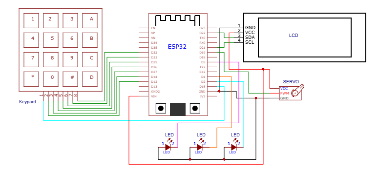
How to build an ESP32-based door access control system using keypad for password authentication
ESP32 ESP-32 Wireless WiFi Bluetooth Development Board, 4 * 4 Matrix Array Matrix Keypad, SG90 9g Mini Micro Servo Motor, 16x2LCD Display with I2C Interface, 3MM LED Red
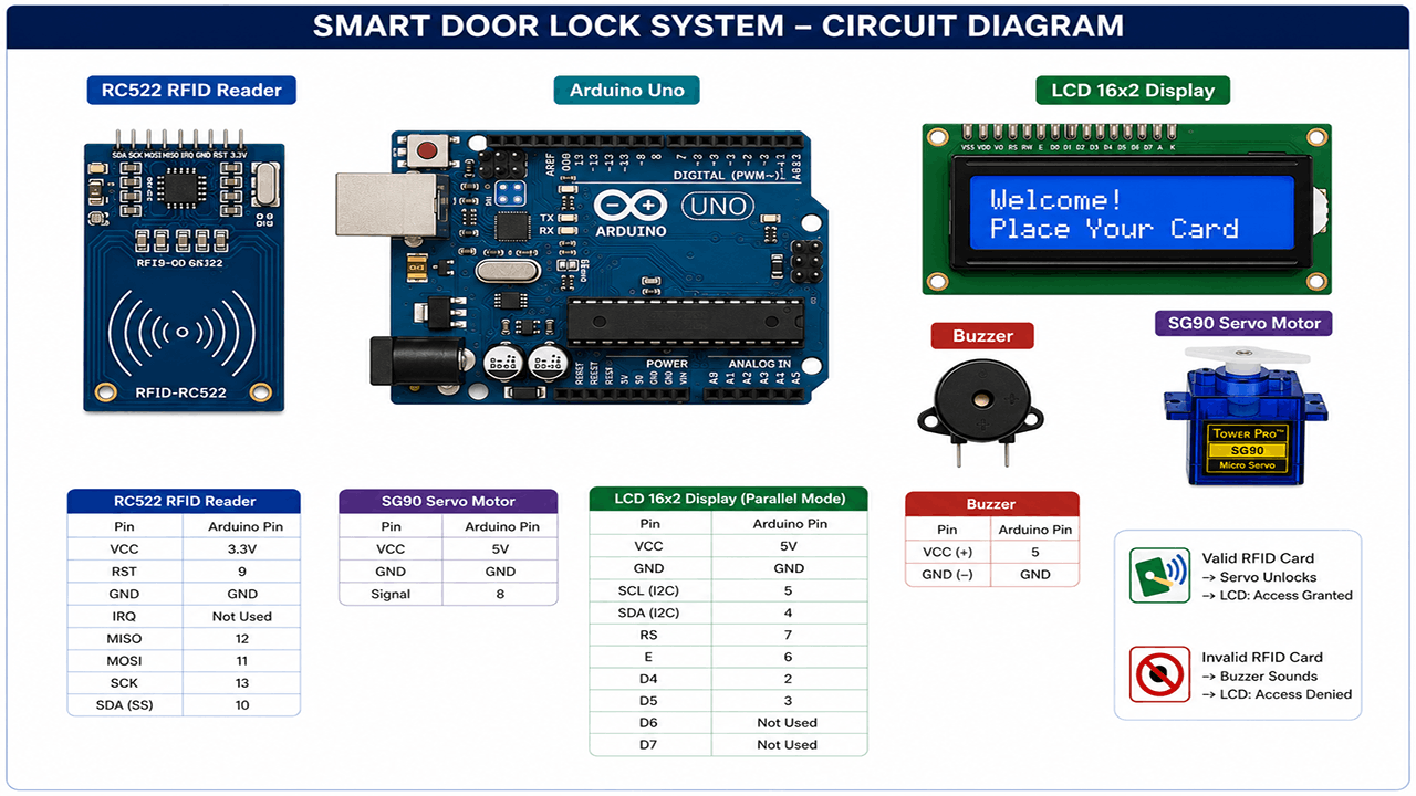
Smart Door Lock with RFID and Servo Motor
Arduino UNO R3 removable IC Chip with USB CABLE, RFID Reader Module 13.56Mhz, SG90 9g Mini Micro Servo Motor, 16x2LCD Display with I2C Interface, 5v active buzzer, Breadboard 830 Point Solderless, Male to Male Jumper Wires
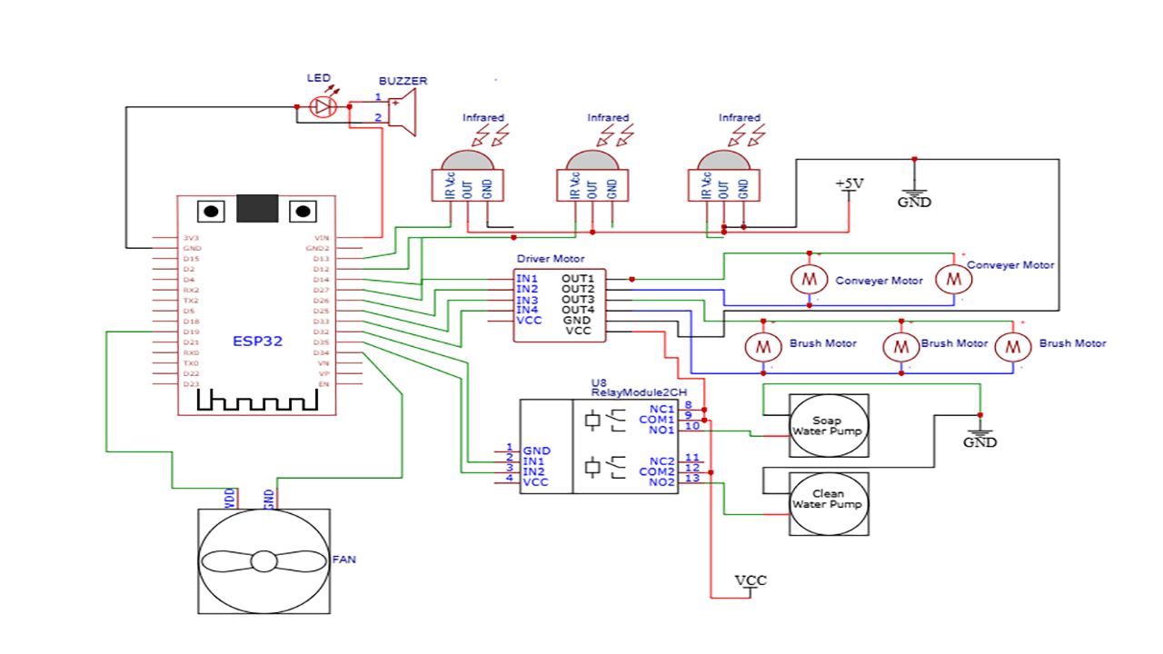
How to build ESP32-based automatic car wash system
The hardware components used in the automatic car wash system include one, ESP32 Development Board (ESP32-WROOM-32 DevKit), Infrared Obstacle Avoidance Tracking Sensor Module, L298N Motor Driver, Single Channel 5v Relay Module, SUBMERSIBLE WATER PUMP DC 3V-5V, YD8010 Cooling Fan 5V, 3MM LED Red, 5V active buzzer, 5V 2A Power Adapter, 12VDC 2A Adapter charger, Male to Male Jumper Wires, Breadboard 830 Point Solderless, terminal blocks or connectors, one main power switch, one fuse for power protection, and mounting hardware such as screws, nuts, and standoffs.
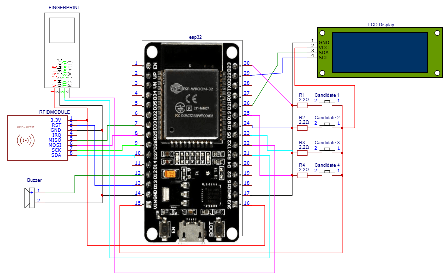
How to build an ESP32-based electronic voting system
ESP32 ESP-32 Wireless WiFi Bluetooth Development Board, 16x2LCD Display with I2C Interface, 5v active buzzer, RFID Reader Module 13.56Mhz, Push Button with cap, AS608 Fingerprint Reader Sensor Module Optical