Smart Door Lock with RFID and Servo Motor
📖 Overview
In this course, you will build a smart door lock system that utilizes RFID technology to grant access to authorized individuals. The system will consist of an Arduino Uno, an RC522 RFID reader, an SG90 servo motor, an LCD 16x2 display, a buzzer, and other supporting components. By the end of the course, you will have a fully functional access control system that can read RFID tags, control a servo motor to lock and unlock a door, and display status messages on an LCD screen.
The system will also feature a buzzer that sounds when an invalid RFID tag is presented, adding an extra layer of security and feedback. You will learn how to connect and program these components to work together seamlessly, creating a robust and reliable access control system. This project is an excellent way to learn about RFID technology, servo motor control, and access control logic, making it a valuable skillset for any aspiring IoT or embedded systems developer.
This course is designed for intermediate learners, assuming a basic understanding of electronics and programming concepts. You will learn how to:
- Connect and configure the RC522 RFID reader with the Arduino Uno
- Control the SG90 servo motor to lock and unlock a door
- Display status messages on an LCD 16x2 screen
- Implement simple access control logic using RFID tags
By completing this course, you will gain hands-on experience with popular hardware components and develop a deeper understanding of the underlying technologies. You will also learn how to design and build a practical and useful project that can be applied to real-world scenarios, making it an excellent addition to your portfolio and skillset.
🔌 Components & Wiring Guide
Components and Their Purposes
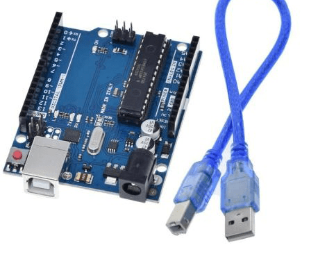
- Arduino Uno: The main microcontroller board that processes all the operations
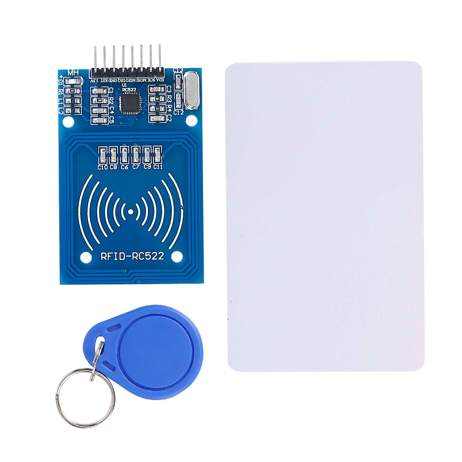
- RC522 RFID reader: Reads the RFID tags and sends the data to the Arduino board
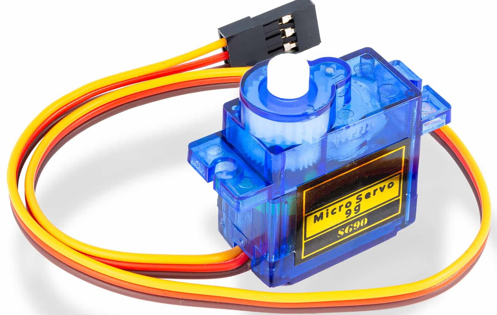
- SG90 servo motor: Used to lock and unlock the door
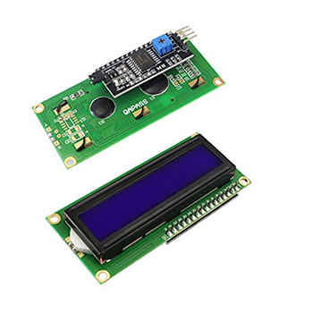
- LCD 16x2 display: Displays the status of the door lock system
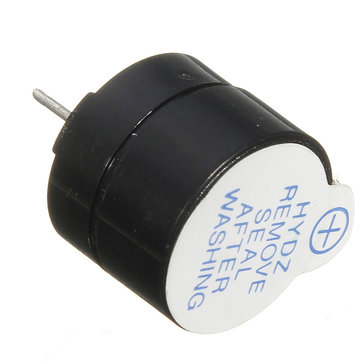
- Buzzer: Sounds an alarm on invalid access attempts
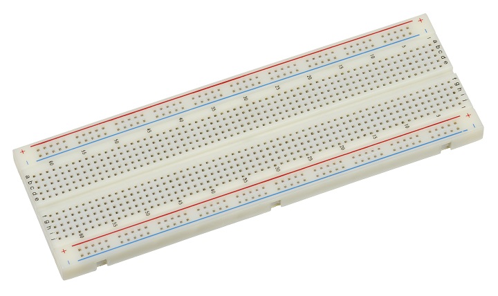
- Breadboard: Used for prototyping and connecting the components
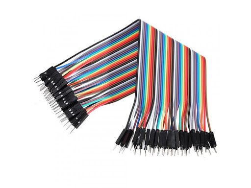
- Jumper wires: Connect the components to the Arduino board and the breadboard
Wiring and Connection Guide
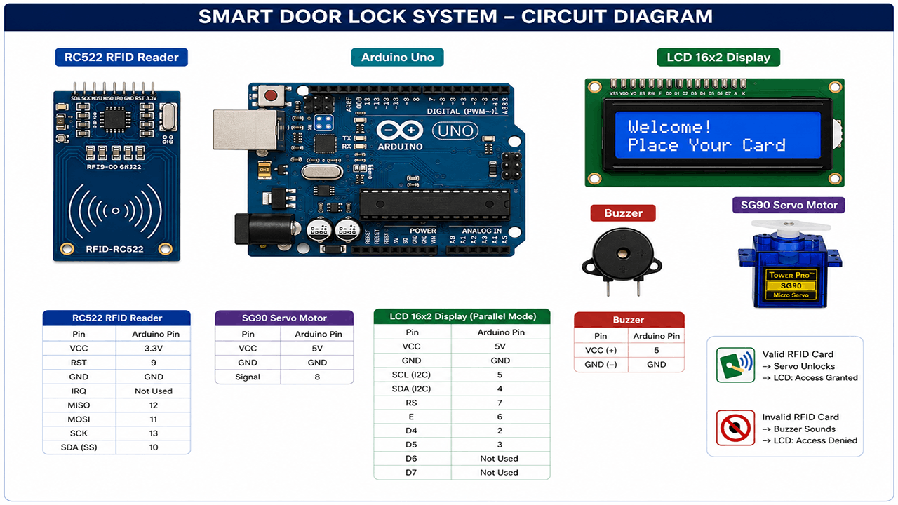
To connect the components, follow these steps: First, connect the Arduino Uno to the breadboard using jumper wires. Connect the 5V pin from the Arduino to the positive rail of the breadboard and the GND pin to the negative rail. Next, connect the RC522 RFID reader to the breadboard. The RC522 module has the following pins: VCC, RST, GND, IRQ, MISO, MOSI, SCK, and SDA. Connect the VCC pin to the 3.3V pin on the Arduino, the RST pin to digital pin 9, the GND pin to the GND pin on the Arduino, the IRQ pin is not used in this project, the MISO pin to digital pin 12, the MOSI pin to digital pin 11, the SCK pin to digital pin 13, and the SDA pin to digital pin 10. Then, connect the SG90 servo motor to the Arduino. The servo motor has three pins: VCC, GND, and Signal. Connect the VCC pin to the 5V pin on the Arduino, the GND pin to the GND pin on the Arduino, and the Signal pin to digital pin 8. After that, connect the LCD 16x2 display to the breadboard. The LCD has the following pins: VCC, GND, SCL, SDA, RS, E, D4, D5, D6, and D7. Connect the VCC pin to the 5V pin on the Arduino, the GND pin to the GND pin on the Arduino, the SCL pin to digital pin 5, the SDA pin to digital pin 4, the RS pin to digital pin 7, the E pin to digital pin 6, the D4 pin to digital pin 2, the D5 pin to digital pin 3, the D6 pin is not used in this project, and the D7 pin is not used in this project. Finally, connect the buzzer to the Arduino. The buzzer has two pins: VCC and GND. Connect the VCC pin to digital pin 5 and the GND pin to the GND pin on the Arduino.| Component | Arduino Pin |
|---|---|
| RC522 RFID reader | 3.3V, 9, GND, 12, 11, 13, 10 |
| SG90 servo motor | 5V, GND, 8 |
| LCD 16x2 display | 5V, GND, 5, 4, 7, 6, 2, 3 |
| Buzzer | 5, GND |
🛠️ Step-by-Step Guide
Introduction to the Smart Door Lock Project
In this project, we will build an RFID-based access control system using an Arduino Uno, RC522 RFID reader, SG90 servo motor, LCD 16x2 display, and a buzzer. This system will unlock a door with an authorized card, show the status on the LCD, and sound a buzzer on invalid attempts.
Step 1: Setting Up the Hardware Components
Start by gathering all the necessary hardware components, including the Arduino Uno, RC522 RFID reader, SG90 servo motor, LCD 16x2 display, buzzer, breadboard, and jumper wires. Make sure all the components are in good condition and properly packaged.
Step 2: Connecting the RFID Reader to the Arduino Uno
Connect the RC522 RFID reader to the Arduino Uno as follows:
- VCC to 3.3V
- RST to digital pin 9
- GND to GND
- MOSI to digital pin 11
- MISO to digital pin 12
- SCK to digital pin 13
- IRQ to digital pin 2 (optional)
Step 3: Connecting the Servo Motor to the Arduino Uno
Connect the SG90 servo motor to the Arduino Uno as follows:
- VCC to 5V
- GND to GND
- Signal to digital pin 10
Step 4: Connecting the LCD Display to the Arduino Uno
Connect the LCD 16x2 display to the Arduino Uno as follows:
- VCC to 5V
- GND to GND
- SCL to digital pin 5
- SDA to digital pin 4
Step 5: Connecting the Buzzer to the Arduino Uno
Connect the buzzer to the Arduino Uno as follows:
- Positive leg to digital pin 8
- Negative leg to GND
Step 6: Writing the Firmware Code
Write the firmware code to read RFID tags, control the servo motor, and manage the access logic. The code should include the following functionalities:
- Reading RFID tags using the RC522 library
- Controlling the servo motor using the Servo library
- Displaying the status on the LCD display
- Sounding the buzzer on invalid attempts
Step 7: Uploading the Firmware to the Arduino Uno
Upload the firmware code to the Arduino Uno using the Arduino IDE. Make sure to select the correct board, processor, and serial port before uploading the code.
Step 8: Testing the Smart Door Lock System
Test the smart door lock system by scanning an authorized RFID tag and verifying that the servo motor unlocks the door and the LCD display shows the correct status. Also, test the system with an invalid RFID tag and verify that the buzzer sounds and the LCD display shows an error message.
Troubleshooting Tips
If the system is not working as expected, check the following:
- Verify that all the connections are correct and secure
- Check the RFID tag and ensure it is properly encoded
- Verify that the servo motor is properly connected and calibrated
- Check the LCD display and ensure it is properly connected and configured
- Verify that the buzzer is properly connected and configured
💻 Sample Code
```cpp
#include <SPI.h>
#include <MFRC522.h>
#include <Servo.h>
#include <LiquidCrystal.h>

// Define constants for pins and variables
const int RST_PIN = 9;         // Reset pin for RC522
const int SS_PIN = 10;         // Slave select pin for RC522
const int SERVO_PIN = 6;       // Pin for servo motor
const int BUZZER_PIN = 8;      // Pin for buzzer
const int LCD_RS = 7;         // RS pin for LCD
const int LCD_E = 2;           // Enable pin for LCD
const int LCD_D4 = 5;          // D4 pin for LCD
const int LCD_D5 = 4;          // D5 pin for LCD
const int LCD_D6 = 3;          // D6 pin for LCD
const int LCD_D7 = A0;         // D7 pin for LCD

// Initialize MFRC522 instance
MFRC522 mfrc522(SS_PIN, RST_PIN);
// Initialize Servo instance
Servo servo;
// Initialize LiquidCrystal instance
LiquidCrystal lcd(LCD_RS, LCD_E, LCD_D4, LCD_D5, LCD_D6, LCD_D7);

// Authorized RFID tag UID
byte authorizedTag[] = {0x12, 0x34, 0x56, 0x78};

void setup() {
  // Initialize serial communication for debugging
  Serial.begin(9600);
  // Initialize SPI bus
  SPI.begin();
  // Initialize MFRC522
  mfrc522.PCD_Init();
  // Initialize servo motor
  servo.attach(SERVO_PIN);
  servo.write(0);  // Initialize servo to locked position
  // Initialize LCD
  lcd.begin(16, 2);
  lcd.setCursor(0, 0);
  lcd.print("Smart Door Lock");
  // Initialize buzzer pin as output
  pinMode(BUZZER_PIN, OUTPUT);
}

void loop() {
  // Look for new cards
  if (!mfrc522.PICC_IsNewCardPresent()) {
    return;
  }
  // Select one of the cards
  if (!mfrc522.PICC_ReadCardSerial()) {
    return;
  }
  // Get the UID of the card
  byte* uid = mfrc522.uid.uidByte;
  byte uidSize = mfrc522.uid.size;
  // Check if the card is authorized
  if (checkAuthorization(uid, uidSize)) {
    // Unlock the door
    servo.write(90);  // Unlock position
    lcd.setCursor(0, 1);
    lcd.print("Access granted");
    delay(2000);
    // Lock the door after 2 seconds
    servo.write(0);  // Lock position
    lcd.setCursor(0, 1);
    lcd.print("                ");
  } else {
    // Invalid card, sound the buzzer
    tone(BUZZER_PIN, 1000, 500);
    lcd.setCursor(0, 1);
    lcd.print("Access denied");
    delay(1000);
    lcd.setCursor(0, 1);
    lcd.print("                ");
  }
}

// Function to check if the RFID tag is authorized
bool checkAuthorization(byte* uid, byte uidSize) {
  // Compare the UID with the authorized tag
  for (byte i = 0; i < uidSize; i++) {
    if (uid[i] != authorizedTag[i]) {
      return false;
    }
  }
  return true;
}
```
📝 Check Your Understanding
1. What is the primary function of the RC522 RFID reader in the smart door lock system?
   a) To control the servo motor
   b) To display status on the LCD
   c) To read RFID tags
   d) To sound the buzzer
   Answer: c

2. Which pin of the Arduino Uno is typically used to connect the servo motor signal wire in this project?
   a) Digital pin 2
   b) Digital pin 9
   c) Analog pin 0
   d) Digital pin 13
   Answer: b

3. What is the purpose of the LCD 16x2 display in the smart door lock system?
   a) To display the RFID tag's unique ID
   b) To show the system's status and access messages
   c) To control the servo motor's angle
   d) To generate a beep sound
   Answer: b

4. How does the system respond to an invalid RFID card attempt?
   a) The servo motor unlocks the door
   b) The LCD displays a welcome message
   c) The buzzer sounds an alert
   d) The system remains idle
   Answer: c

5. In the code, what is the purpose of the delay() function when controlling the servo motor?
   a) To read the RFID tag's data
   b) To display a message on the LCD
   c) To allow the servo motor to reach its target position
   d) To connect to an external database
   Answer: c
Need the Components for This Project?
If you don't already have the components listed above, you can buy genuine Arduino, ESP32, Raspberry Pi, sensors, and other electronic components from SoftTech Supply Shop, with fast delivery across Kigali and other parts of Rwanda.
← Browse more Arduino & IoT tutorialsRelated Tutorials
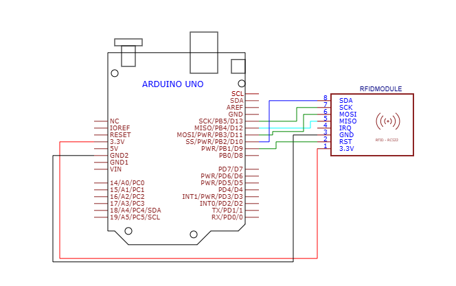
How to use RFID Reader Module 13.56Mhz with an Arduino UNO
RFID Reader Module 13.56Mhz, Arduino Uno R3 With USB Cable, Male to Male Jumper Wires, Breadboard 830 Point Solderless
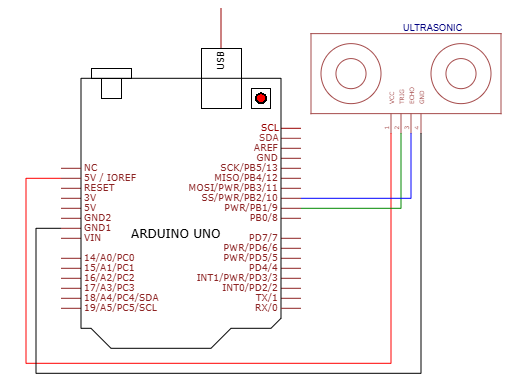
How to use HC-SR04 Ultrasonic Sensor on Arduino UNO
HC-SR04 Ultrasonic Sensor, Arduino Uno R3 With USB Cable, Male to Male Jumper Wires, Breadboard 830 Point Solderless
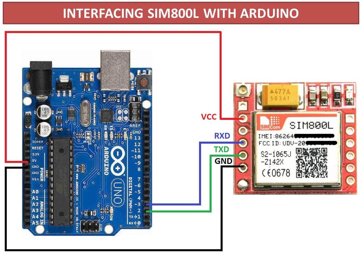
How to connect GSM SIM800L with Arduino Uno to send an SMS or make a Call
Arduino UNO R3 removable IC Chip with USB CABLE, Smallest SIM800L GPRS GSM, Male to Female jumper wires
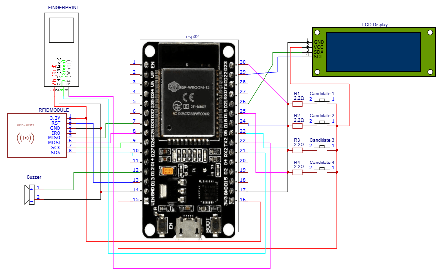
How to build an ESP32-based electronic voting system
ESP32 ESP-32 Wireless WiFi Bluetooth Development Board, 16x2LCD Display with I2C Interface, 5v active buzzer, RFID Reader Module 13.56Mhz, Push Button with cap, AS608 Fingerprint Reader Sensor Module Optical