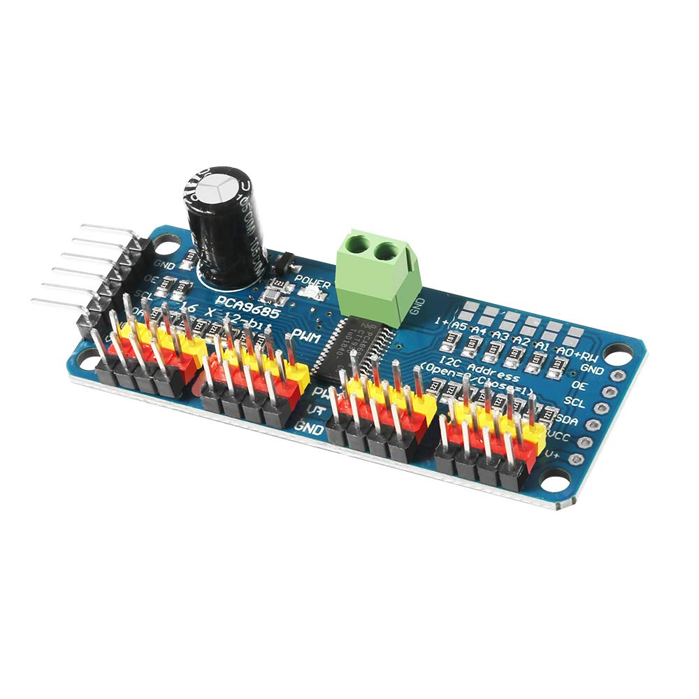

PCA9685PW 16 Channel Servo Driver-I2C interface
Price:
RWF 13,000Added to Cart!
Need help or have questions about this product?
Contact STS Support →Product Description
- Dimensions (no headers or terminal block) 2.5" x 1" x 0.1" (62.5mm x 25.4mm x 3mm)
- Weight (no headers or terminal block): 5.5grams
- Weight (with 3x4 headers & terminal block): 9grams
- This board/chip uses I2C 7-bit address between 0x60-0x80, selectable with jumpers.
- Terminal block for power input (or you can use the 0.1" breakouts on the side)
- Reverse polarity protection on the terminal block input
- Green power-good LED
- 3 pin connectors in groups of 4 so you can plug in 16 servos at once (Servo plugs are slightly wider than 0.1" so you can only stack 4 next to each other on 0.1" header
- "Chain-able" design
- A spot to place a big capacitor on the V+ line (in case you need it)
- 220-ohm series resistors on all the output lines to protect them, and to make driving LEDs trivial.
- Solder jumpers for the 6 address select pins.
- i2c-controlled PWM driver with a built-in clock. Unlike the TLC5940 family, you do not need to continuously send it signal tying up your microcontroller, its completely free running!
- It is 5V compliant, which means you can control it from a 3.3V microcontroller and still safely drive up to 6V outputs (this is good for when you want to control white or blue LEDs with 3.4+ forward voltages)
- 6 address select pins so you can wire up to 62 of these on a single i2c bus, a total of 992 outputs - that's a lot of servos or LEDs
- Adjustable frequency PWM up to about 1.6 KHz
- 12-bit resolution for each output - for servos, that means about 4us resolution at 60Hz update rate
- Configurable push-pull or open-drain output
- Output enable pin to quickly disable all the outputs.
- (1) Drive board connected to Arduino:
- The PWM driver board uses the I2C method, so only four lines can be connected to the Arduino device:
- "Classic" Arduino pin mode:
- + 5v -> VCC
- GND -> GND
- Analog 4 -> SDA
- Analog 5 -> SCL
- Old Mega pin way:
- + 5v -> VCC
- GND -> GND
- Digital 20 -> SDA
- Digital 21 -> SCL
- R3 and later Arduino pin method (Uno, Mega &
- Leonardo):
- (These boards have dedicated SDA and SCL pins)
- + 5v -> VCC
- GND -> GND
- SDA -> SDA
- SCL -> SCL
- VCC pin is only for the chip power supply, if you want to connect the servo or LED lights, use the V + pin power supply, V + pin supports 3.3 ~ 6V power supply (chip safe voltage 5V). It is recommended to connect the external power supply via the power supply terminal.
- (2) power supply part:
- Most of the servo design voltage is 5 ~ 6V, especially in a number of steering gear at the same time running, with the need for high-power power supply. If you are directly using the Arduino 5V pin to power the servo directly, there are some unpredictable problems, so we recommend that you have a suitable external power supply for the drive board.
- (3) Connect the servo:
- Most servos are connected using standard 3-wire female plugs, as long as the corresponding pin into the driver board on it. (Ground wire is generally black or brown, the signal line is generally yellow or white)
- (4) for the driver board assigned address:
Why Buy from SoftTech Supply?
- Genuine electronic components from trusted suppliers
- Competitive prices on Arduino, Raspberry Pi, sensors & more
- Fast delivery across Kigali and Rwanda
- Expert technical support and project consultation
- Easy returns and quality guarantee
Related Products
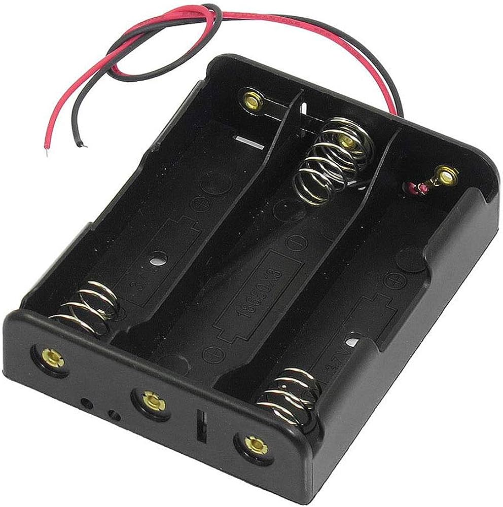
3.7V 3 Slot 18650 Battery holder
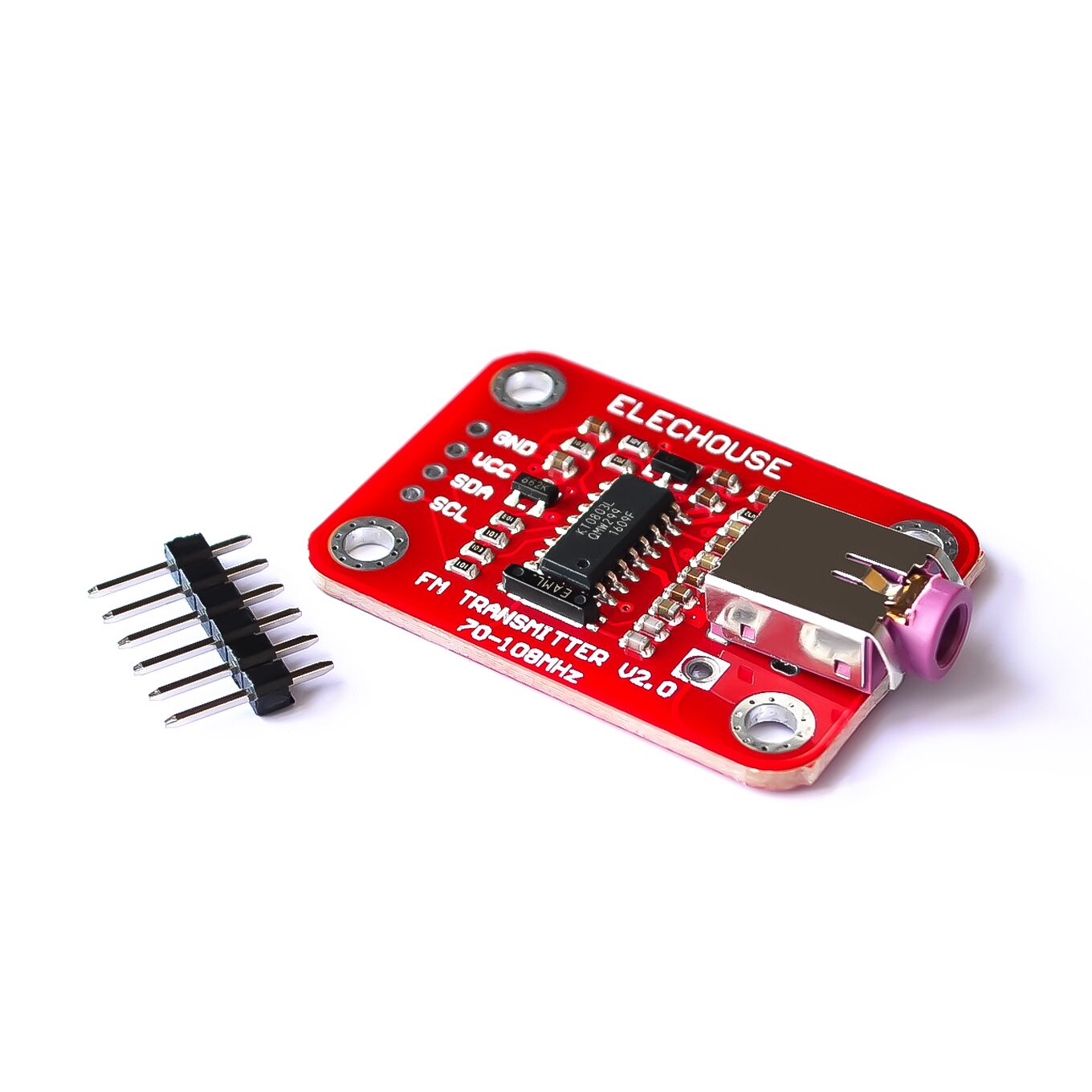
HW-097 MAX485 TTL to RS485 Modbus Module
You can buy PCA9685PW 16 Channel Servo Driver-I2C interface at STS - Kigali, Rwanda or we delivery to you
This product is available at SoftTech Supply, your trusted electronics shop in Kigali, Rwanda. We stock genuine electronic components including Arduino boards, Raspberry Pi, ESP32, ESP8266, various sensors, motors, displays, and thousands of other components for your IoT, embedded systems, and electronics projects. Visit our shop or order online for fast delivery across Rwanda. Need help selecting components or implementing your project? Contact STS for expert technical support and consultation.