How to build a line tracking robot using Arduino UNO AND infrared sensor
📖 Overview
In this intermediate-level course, students will build a line tracking robot using an Arduino UNO and infrared sensors. The robot will be able to follow a black line on a lighter surface, making adjustments in real-time to stay on course. This project is a great way to learn about robotics, sensor integration, and autonomous systems, all while developing problem-solving skills and hands-on experience with electronics and programming.
Through this project, students will learn how to read signals from infrared sensors, control DC motors using an L293D motor driver shield, and write Arduino code to make decisions based on sensor input. They will also understand how to power their robot using a 7.4V battery pack and how to integrate all the components into a single system. By the end of the course, students will have a fully functional line tracking robot that can be used in a variety of applications, from agriculture to security and smart-home solutions.
The skills and knowledge gained in this course will be useful for anyone interested in robotics, automation, and IoT development. In the context of East Africa, where agriculture is a significant sector, line tracking robots can be used to automate crop monitoring, irrigation systems, and harvesting processes. Additionally, these robots can be used in security systems to patrol borders or monitor premises. By building and programming their own line tracking robot, students will gain a deeper understanding of the possibilities and challenges of robotics and automation in real-world applications.
Some of the key topics covered in this course include:
- Introduction to Arduino UNO and its applications
- Understanding infrared sensors and their use in line tracking
- Controlling DC motors using an L293D motor driver shield
- Writing Arduino code for sensor integration and motor control
- Powering and integrating all components into a single system
By completing this course, students will have a solid foundation in robotics and automation, as well as the skills and confidence to design and build their own projects using Arduino and other microcontrollers. Whether you're a student, hobbyist, or professional, this course is a great way to learn about the exciting world of robotics and automation.
🔌 Components & Wiring Guide
Components & Wiring Guide
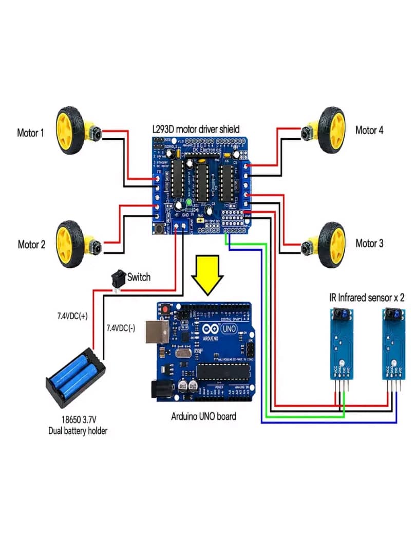
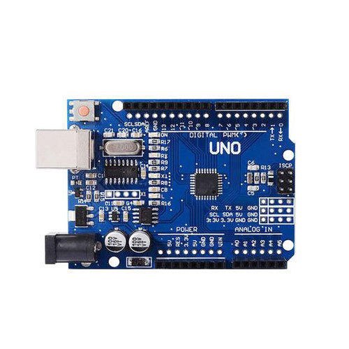
The following components are required to build the line tracking robot:- Arduino Uno: Acts as the brain of the robot, reading signals from IR sensors and controlling motor movement.
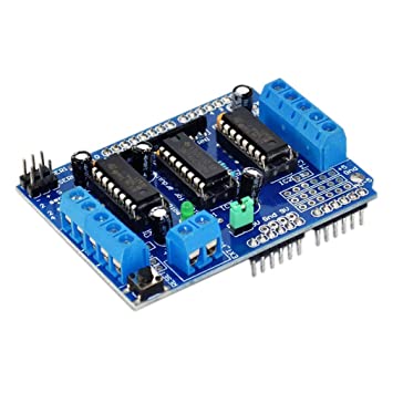
- L293D Motor Driver Shield: Controls direction and speed of DC motors and supplies current to drive them.
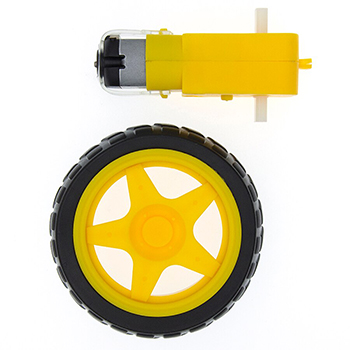
- Four DC Motors: Provide movement for the robot's four wheels.
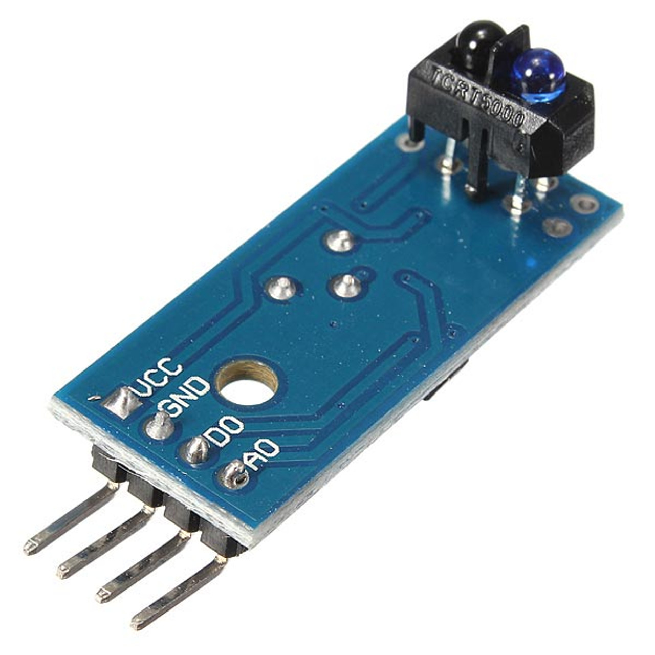
- Two IR Infrared Sensors: Detect difference between black line and lighter surface.
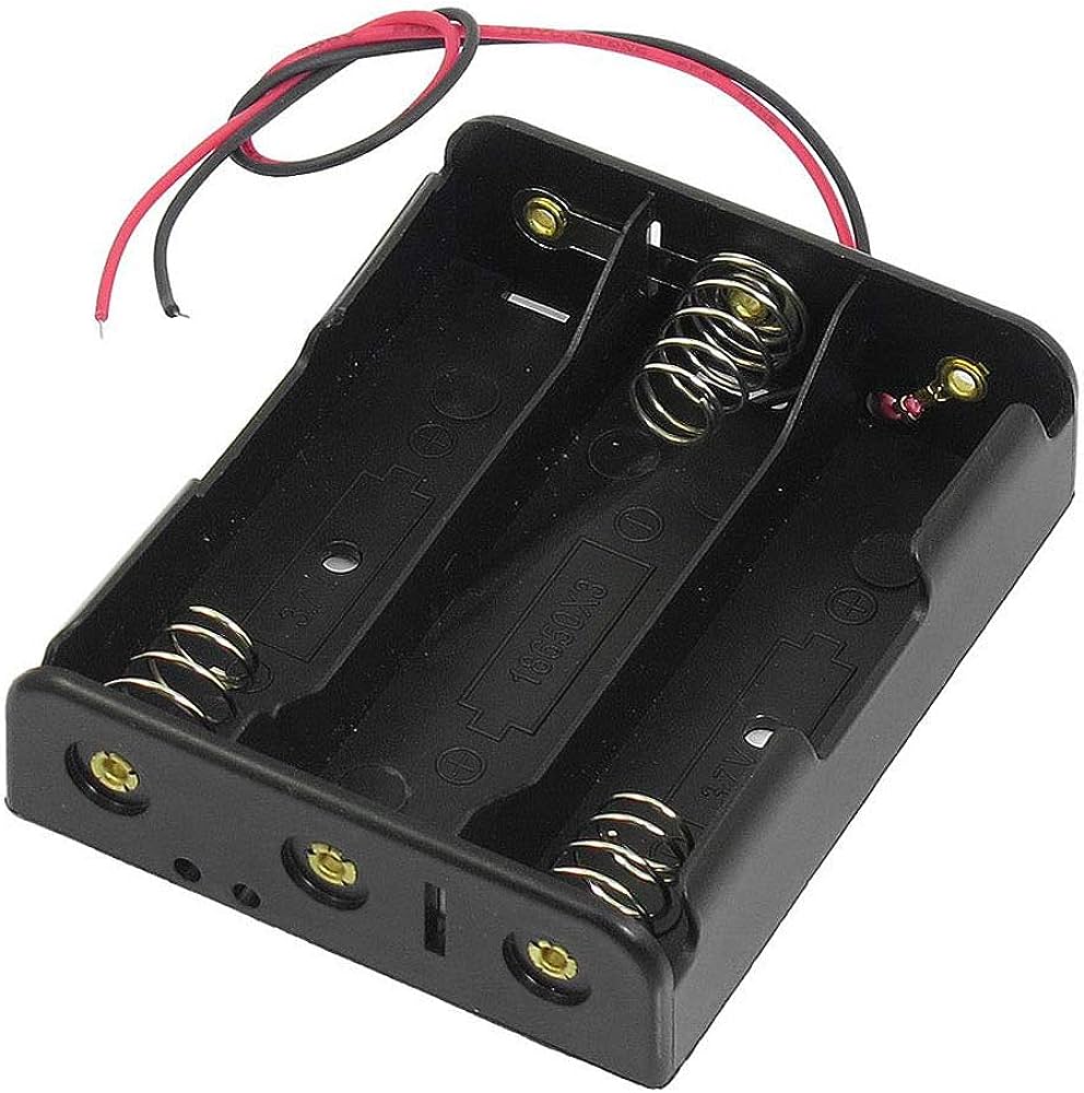
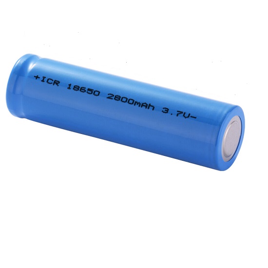
- 7.4 V Battery Pack: Supplies power to Arduino and motor driver.
Wiring the Components
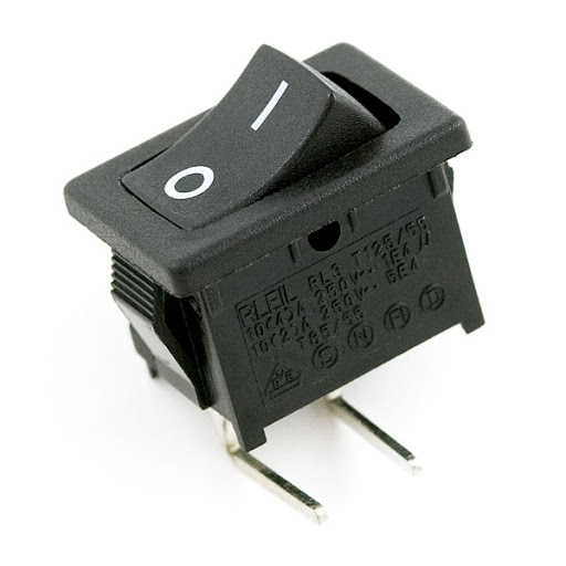
To connect the components, follow these steps: The Arduino Uno is the central component, and all other components connect to it. Start by mounting the L293D Motor Driver Shield on top of the Arduino Uno. This shield has screw terminals for connecting the motors and a voltage input for the battery pack. Connect the 7.4 V battery pack to the VIN and GND pins on the Arduino Uno, making sure to use a power switch to control power supply. Next, connect the four DC motors to the output terminals on the L293D Motor Driver Shield. The motor connections are as follows:| Motor | L293D Terminal |
|---|---|
| Left Front | Output 1 and 2 |
| Right Front | Output 3 and 4 |
| Left Rear | Output 5 and 6 |
| Right Rear | Output 7 and 8 |
Safety Note
When working with batteries and motors, ensure you handle them with care. Avoid short circuits, and do not touch electrical components with wet hands or while standing on a conductive surface. If you are not experienced with electronics, consider seeking guidance from an experienced instructor or mentor.🛠️ Step-by-Step Guide
Introduction to Line Tracking Robot
In this tutorial, we will build a line tracking robot using Arduino Uno and infrared sensors. This robot can be used in various applications such as agriculture, security, or smart-home solutions in Rwanda and East Africa. The robot follows a black line on a lighter surface, making it a great project for intermediate electronics enthusiasts.
Hardware Components and Setup
To start, gather all the necessary hardware components, which can be sourced from SoftTech Supply in Kigali, Rwanda. The components include:
- Arduino Uno
- L293D motor driver shield
- Four DC motors
- Two IR infrared sensors
- 7.4 V battery pack (2 × 18650 cells)
Mount the L293D motor driver shield on the Arduino Uno, ensuring proper alignment of the pins. Connect the four DC motors to the motor driver shield, following the shield's documentation for correct pin connections.
Wiring Recap
Connect the IR infrared sensors to the Arduino Uno as follows:
- VCC pin to 5V on the Arduino
- GND pin to GND on the Arduino
- OUT pin to digital pin 2 (left sensor) and digital pin 3 (right sensor) on the Arduino
Connect the 7.4 V battery pack to the Arduino Uno and the motor driver shield through the power switch. Ensure the switch is turned off during the wiring process.
Firmware Upload
Write the Arduino code to read the signals from the IR sensors and control the motors accordingly. The code should include:
- Pin definitions for the IR sensors and motors
- Functions to read the IR sensor values and adjust the motor speeds
- A main loop to continuously read the IR sensors and update the motor speeds
Upload the code to the Arduino Uno using the Arduino IDE. Ensure the board and port settings are correct before uploading.
Testing and Troubleshooting
Once the code is uploaded, turn on the power switch and place the robot on a surface with a black line. The robot should follow the line, adjusting its direction as needed. If the robot does not follow the line correctly, check the following:
- IR sensor connections and alignment
- Motor connections and wiring
- Code logic and pin definitions
- Battery voltage and power switch functionality
Adjust the code or hardware as needed to resolve any issues. Remember to handle the robot with care, avoiding any situations that may cause damage or injury.
Safety Note
When working with electronics, especially those involving mains voltage, high current, or heat, it is essential to take necessary safety precautions. Although this project does not involve mains voltage, be cautious when handling the battery pack and motors to avoid any potential electrical shocks or injuries.
💻 Sample Code
// Define the pins for the IR sensors
const int leftIRSensor = 2;
const int rightIRSensor = 3;

// Define the pins for the motor driver
const int motor1Forward = 4;
const int motor1Backward = 5;
const int motor2Forward = 6;
const int motor2Backward = 7;
const int motor3Forward = 8;
const int motor3Backward = 9;
const int motor4Forward = 10;
const int motor4Backward = 11;

// Define the speed of the motors
const int motorSpeed = 200;

void setup() {
  // Initialize the IR sensor pins as inputs
  pinMode(leftIRSensor, INPUT);
  pinMode(rightIRSensor, INPUT);

  // Initialize the motor driver pins as outputs
  pinMode(motor1Forward, OUTPUT);
  pinMode(motor1Backward, OUTPUT);
  pinMode(motor2Forward, OUTPUT);
  pinMode(motor2Backward, OUTPUT);
  pinMode(motor3Forward, OUTPUT);
  pinMode(motor3Backward, OUTPUT);
  pinMode(motor4Forward, OUTPUT);
  pinMode(motor4Backward, OUTPUT);
}

void loop() {
  // Read the values from the IR sensors
  int leftSensorValue = digitalRead(leftIRSensor);
  int rightSensorValue = digitalRead(rightIRSensor);

  // If both sensors detect the line, move straight
  if (leftSensorValue == HIGH && rightSensorValue == HIGH) {
    moveForward();
  }
  // If the left sensor loses the line, turn left
  else if (leftSensorValue == LOW && rightSensorValue == HIGH) {
    turnLeft();
  }
  // If the right sensor loses the line, turn right
  else if (leftSensorValue == HIGH && rightSensorValue == LOW) {
    turnRight();
  }
  // If both sensors lose the line, stop
  else {
    stopMotors();
  }

  delay(50); // Adjust the speed of the robot
}

// Function to move the robot forward
void moveForward() {
  analogWrite(motor1Forward, motorSpeed);
  analogWrite(motor2Forward, motorSpeed);
  analogWrite(motor3Forward, motorSpeed);
  analogWrite(motor4Forward, motorSpeed);
  digitalWrite(motor1Backward, LOW);
  digitalWrite(motor2Backward, LOW);
  digitalWrite(motor3Backward, LOW);
  digitalWrite(motor4Backward, LOW);
}

// Function to turn the robot left
void turnLeft() {
  analogWrite(motor1Forward, motorSpeed);
  analogWrite(motor2Forward, motorSpeed);
  analogWrite(motor3Backward, motorSpeed);
  analogWrite(motor4Backward, motorSpeed);
  digitalWrite(motor1Backward, LOW);
  digitalWrite(motor2Backward, LOW);
  digitalWrite(motor3Forward, LOW);
  digitalWrite(motor4Forward, LOW);
}

// Function to turn the robot right
void turnRight() {
  analogWrite(motor1Backward, motorSpeed);
  analogWrite(motor2Backward, motorSpeed);
  analogWrite(motor3Forward, motorSpeed);
  analogWrite(motor4Forward, motorSpeed);
  digitalWrite(motor1Forward, LOW);
  digitalWrite(motor2Forward, LOW);
  digitalWrite(motor3Backward, LOW);
  digitalWrite(motor4Backward, LOW);
}

// Function to stop the motors
void stopMotors() {
  digitalWrite(motor1Forward, LOW);
  digitalWrite(motor2Forward, LOW);
  digitalWrite(motor3Forward, LOW);
  digitalWrite(motor4Forward, LOW);
  digitalWrite(motor1Backward, LOW);
  digitalWrite(motor2Backward, LOW);
  digitalWrite(motor3Backward, LOW);
  digitalWrite(motor4Backward, LOW);
}
📝 Check Your Understanding
1. What is the primary function of the L293D Motor Driver Shield in the line tracking robot?
   a) To read signals from the IR sensors
   b) To supply power to the Arduino Uno
   c) To control the direction and speed of the DC motors
   d) To detect the black line and lighter surface
   Answer: c

2. How do the two IR infrared sensors work together to guide the robot?
   a) One sensor detects the line and the other detects obstacles
   b) One sensor monitors the left side and the other monitors the right side of the line
   c) Both sensors detect the line and the robot moves straight if they disagree
   d) The sensors detect the line and send signals to the motor driver directly
   Answer: b

3. What happens when the left IR sensor loses the line while the robot is moving?
   a) The robot turns right
   b) The robot stops moving
   c) The robot turns left
   d) The robot moves backwards
   Answer: c

4. What is the purpose of the 7.4 V battery pack in the line tracking robot?
   a) To power the IR sensors only
   b) To supply power to the motor driver and the Arduino Uno
   c) To charge the DC motors
   d) To detect the line and send signals to the Arduino
   Answer: b

5. What is the role of the Arduino Uno in the line tracking robot?
   a) To control the speed of the DC motors
   b) To detect the black line and lighter surface
   c) To read signals from the IR sensors and decide how the motors should move
   d) To supply power to the motor driver
   Answer: c
Need the Components for This Project?
If you don't already have the components listed above, you can buy genuine Arduino, ESP32, Raspberry Pi, sensors, and other electronic components from SoftTech Supply Shop, with fast delivery across Kigali and other parts of Rwanda.
← Browse more Arduino & IoT tutorialsRelated Tutorials
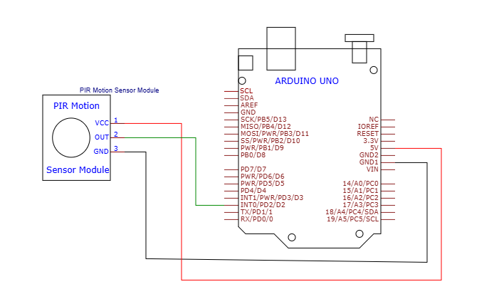
How to Use the HC-SR501 PIR Motion Sensor Module with an Arduino Uno
Arduino Uno R3 With USB Cable, Male to Male Jumper Wires, Breadboard 830 Point Solderless, HC-SR501 PIR module Sensor Detector Module
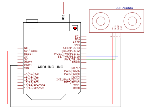
How to use HC-SR04 Ultrasonic Sensor on Arduino UNO
HC-SR04 Ultrasonic Sensor, Arduino Uno R3 With USB Cable, Male to Male Jumper Wires, Breadboard 830 Point Solderless
How to Install the Arduino IDE and Get Started on Your Computer
Computer, Internet connection, Arduino Uno R3 With USB Cable
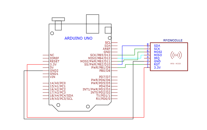
How to use RFID Reader Module 13.56Mhz with an Arduino UNO
RFID Reader Module 13.56Mhz, Arduino Uno R3 With USB Cable, Male to Male Jumper Wires, Breadboard 830 Point Solderless